Remove the RS232 plate from the Huber unit (4 screws), and disconnect the cable on the back. There is another cable inside (which may be slightly hidden; it’s labelled -WVL3) that connects to the back of the internal Com.G@te plate.
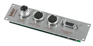
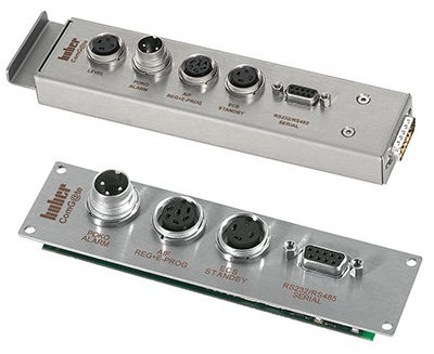
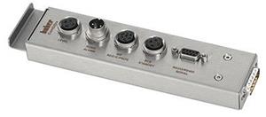
The Com.G@tes provide the following interfaces:
Additional considerations when working at high or low temperatures are the temperature limits of your circulator (remembering that the temperature range of the process will be narrower than this) and thermal fluid (especially regarding high viscosity at low temperatures and inert gas blanketing at high temperatures). If you chose to work beyond our recommended temperature guidelines, this would be at your own risk. One potential issue is that PTFE (used for many Reactor-Ready parts) can soften when used at very high temperatures.
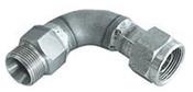
We recommend them for use with circulators (typically Huber units), one for each hose. They are inserted between the hose and its respective hose connection on the circulator. Highly insulated circulator hoses are not very flexible, and Huber hose connections point straight out of the side or back of the unit. Depending on where you want to locate the circulator relative to your reaction system, including the 90° bends can make it easier to position the hoses in the appropriate direction. Choose 90° bends that are the same size as your circulator hose (pump) connections. The part numbers are:

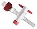
The calibration bend would be mounted on the Huber outlet, and has a sensor pocket for inserting the reference sensor. There are different types of calibration bends, for different sized Huber fittings and sensor diameters. (It is not possible to remove the internal sensor from the Huber unit to calibrate it.) If your Huber unit has a Pilot ONE controller, you can then offset the current temperature reading to match the reference temperature. Navigate to Menu → System Settings → Sensor Adjustment. With Professional or Exclusive levels (E-grades) of the Pilot ONE software, you can calibrate 5 points (5 different temperatures); with the Basic software, a 2-point calibration is possible.

You would first need to ensure that the circulator has enough space in its expansion tank to accept the oil. (An additional external expansion tank can be added to a Huber if required.) The circulator would have to be positioned below the Lara, as gravity is used for drain-down. To drain the Lara vessel jacket:

We can supply a cable for connecting to RS485 interface on the Com.G@te – part number HB6279. This has an open end, for wiring into your application. Further wiring guidance The pinout of the interface is as follows: